Company · Projects & results
Projects from practice
Would you like to know how we work? Here are projects from practice – anonymous, with the quantities and hours from our project records.
Case studies
Industry, scale, task, solution, result – without names. Source of all figures: our project records, as of 08.10.2026; hours rounded.
Catalyst replacement at combined heat and power plants – as a series
Industry: Energy – exhaust gas cleaning of combined heat and power plants (for a plant manufacturer)
Scale: 26 projects in series; for 10 completed projects about 11–67 h, median about 27 h. Example project: 20 scans, 99 recognized pipelines, 22 isometrics, 10 orthos, about 37 h.
Your goal: You want to replace or retrofit catalysts in an operating plant – with a design that matches the plant as built.
Our solution: Survey by laser scanner, pipe recognition with EdgeWise, design in AutoCAD Plant 3D, clash detection in Navisworks.
Result: About 50–140 delivery PDFs per project (isometrics, orthos, model drawings); the workflow repeats as a series.
From scan to Plant 3D model with isometrics
Scope: 24 scans, 55 detected lines, 71 isometrics, 14 orthos, 39 model drawings, about 65 h.
Your goal: You want an existing plant as an up-to-date 3D model – as the basis for modification and documentation.
Our solution: Survey, pipe detection with EdgeWise, Plant 3D model, orthos and isometrics directly from the model.
Result: 104 PDFs in the delivery.
Piping specs and catalogs for a plant manufacturer in water and wastewater engineering
Industry: Plant engineering for water and wastewater treatment
Scope: 12 catalogs, 21 piping spec files; main project about 84 h, about 174 h across 8 projects.
Your goal: You want piping specs to DINDIN – German Institute for Standardization “DIN” before a number means that the standard is published in Germany by the German Institute for Standardization. Background and sources › and ASMEASME – American Society of Mechanical Engineers US engineering society. Its codes for piping, flanges and pipe dimensions apply in many plants worldwide. Background and sources › that work in the project right away – including administration and P&IDR&I – Piping and instrumentation diagram Flow diagram showing all pipes, valves, equipment and instrumentation of a plant (P&ID, Piping and Instrumentation Diagram). Background and sources › assignment.
Our solution: Catalogs and piping specs built, Plant 3D administered, P&ID objects assigned; followed by further projects and support.
Result: Collaboration over 6 years.
Introducing Plant 3D at a chemical company
Industry: Chemicals
Scope: 5 projects, about 153 h in total; one project with 23 P&ID drawings.
Your goal: You want to introduce AutoCAD Plant 3D in your own team and complete the first projects reliably.
Our solution: Template project, training project and supported first projects (P&ID, 3D, orthos).
Result: Deliveries with 42 and 60 PDFs.
Large laser scanning project with more than 400 scans
Scope: 425 registered scans, about 154 h (of which about 54 h on site, registration about 98 h).
Your goal: You want a large existing site captured completely and registered as a point cloud.
Our solution: Survey with a laser scanner, registration in ReCap, review in Navisworks.
Result: Registered point cloud; about 0.23 h of office work per scan for registration.
From our support
Three cases from our support – without names. Source: our support evaluation, as of 08.10.2026; hours rounded.
Project template to company standard
Your goal: You want P&ID projects with your own tag formats, annotations, title block, lists and layers by medium.
Our solution: Configuration implemented, tested and delivered by us and set up at the workstation; follow-up changes via the support quota.
Result: A uniform project template in use; comparable setups recently about 7–10 h (2025/2026).
Large 3D models editable again
Your goal: You want to edit drawings with imported manufacturer models (up to 300 MB) smoothly again.
Our solution: Models simplified or replaced by Plant 3D objects, split into several DWGs, detail models in Navisworks.
Result: Editable again – in about 2.5 h in two sessions.
Clean data transfer from P&ID to the 3D model
Your goal: You want tags, valves and insulation thickness to arrive completely in the 3D model.
Our solution: Configuration checked, transfer set up, workflow as a screencast, example project with a to-do list.
Result: The transfer works – about 3.7 h in three sessions.
389 documented support contacts – median 30 minutes per contact.
Before you go …
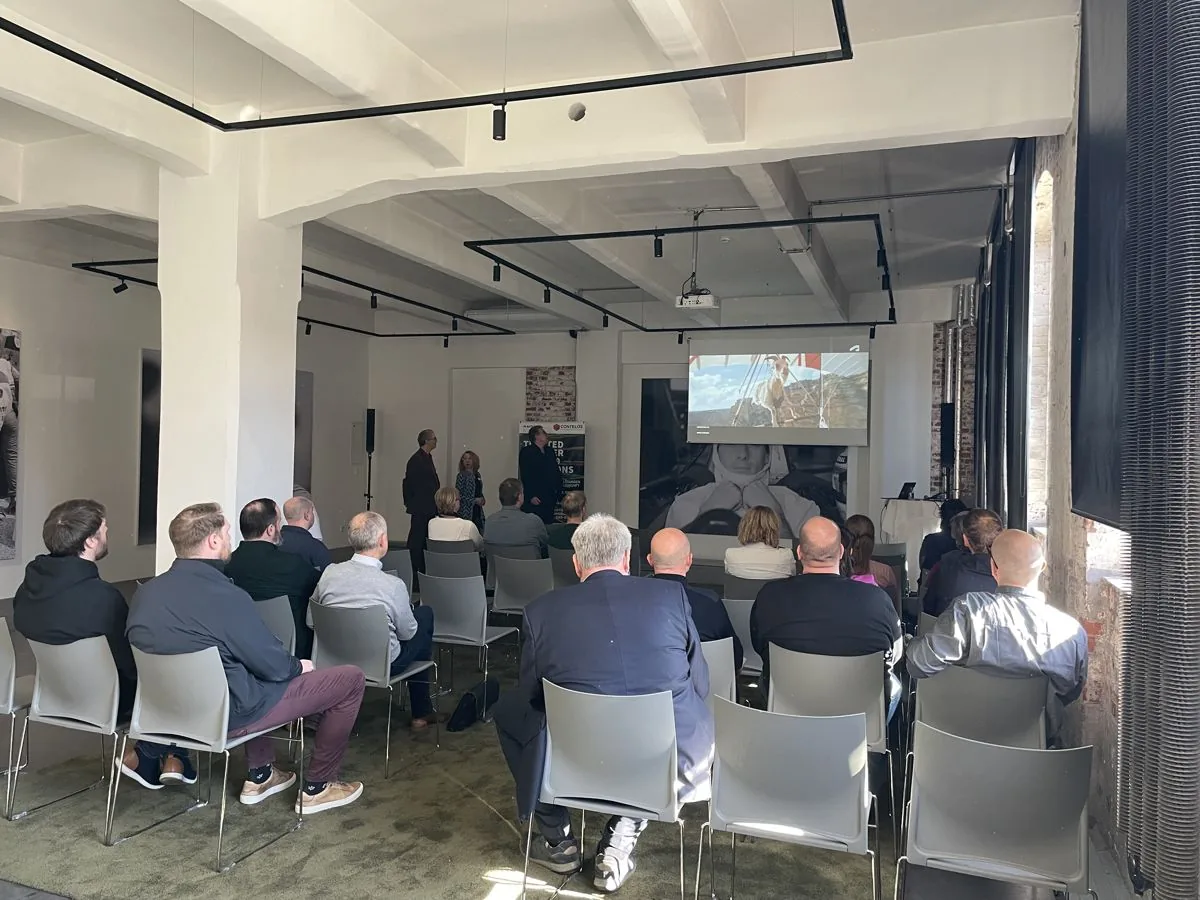
Don't miss any training dates, C³ invitations and news on AutoCAD Plant 3D and P&ID.
Our newsletter only arrives when there's something important – concise and with tips from practice.
Terms, background and sources 3 terms on this page
Brief explanations for reference. They do not replace the standard or code itself.
- DIN – German Institute for Standardization
“DIN” before a number means that the standard is published in Germany by the German Institute for Standardization.
DIN was founded in 1917 as the Standards Committee of German Industry. If “DIN EN” or “DIN EN ISO” precedes the number, a European or international standard has been adopted unchanged as a German standard.
- ASME – American Society of Mechanical Engineers
US engineering society. Its codes for piping, flanges and pipe dimensions apply in many plants worldwide.
ASME was founded in 1880. Well-known codes: B31.3 (process piping), B16.5 (flanges), B36.10M and B36.19M (pipe dimensions).
- R&I – Piping and instrumentation diagram
Flow diagram showing all pipes, valves, equipment and instrumentation of a plant (P&ID, Piping and Instrumentation Diagram).
Symbols and drawing rules: DIN EN ISO 10628-1 and -2. Identification letters for instrumentation: DIN EN 62424 or ISA-5.1.