
Solutions · Project deployment
Project support: plant design with AutoCAD Plant 3D
Plant 3D in your ongoing project: we set up the project, implement standards and work alongside you – as users who know the software inside out. For individual phases or long-term in your team, remote or on site.
The task
Plant 3D in a running project – without standstill.
What you want
- You want to master peak loads, special tasks and new standards in the project.
- You want reinforcements to contribute right away.
Our solution
- Set up the project, implement standards, work along – remote or on site.
- Specialists who know the software inside out.
Your advantage
- Meet deadlines despite peaks.
- Special know-how exactly when needed.
- One contact for software and application.
- Knowledge stays documented in the project.
What we take on
CAD design & plant design
Equipment layout, piping and steel structure design in Plant 3D.
Piping specs & piping design
Create classes, design lines, derive isometrics.
Plant 3D projects
Set up the project, implement standards, support the team.
Bottlenecks & project peaks
Additional capacity without new hires and lengthy onboarding.
Coordination & as-built data
Project coordination, data management, documentation.
Migration & implementation
Migration from legacy systems, network and workgroup structures.
What changes for you
Without support
- Finding and training new people – or putting an extra load on your own team.
- Project standards (identification, piping specs, template) are created on the side during the ongoing project.
With us
- Specialists who know AutoCAD Plant 3D inside out – over 100 projects since 2020 (10 hours or more) according to our project records.
- Example of an introduction in the chemical industry: 5 projects, around 153 h in total – with a template project, a training project and supported first projects.
- Example from water and wastewater engineering: piping specs and catalogs, then follow-up projects and support – collaboration over 6 years.
What you avoid
- A project start without a fixed standard, which later leads to rework on tags and lists.
- Knowledge that leaves with the project.
What you get
- Your project to your standard – remotely or on site.
- Data and documentation are handed over to you.
Figures from our project records and support evaluation, without customer names. As of 7 Nov 2026.
Experience you can read up on
What we learn in projects flows into the Plant Engineering Infobase, our work aids and technical books – so you can see in advance how we work.
Project workflow & standards
Project setup checklist, project routing slip, revisions checklist – our workflows as PDF.
Plant identification
KKS, AKS, RDS-PP and DIN EN IEC 81346 – how we implement plant identification in P&ID and Plant 3D.
Piping specs & pipework
Piping specs, materials, connections and pipework – fundamentals from project practice.
Revision & approval
Keep revision statuses, approvals and documentation traceable in the project.
Existing plant & laser scan
From scan to model: planning, registration and practical values from as-built projects.
Technical books
Compendiums on project start, setup, isometrics and support concepts as PDF.
CAD migration
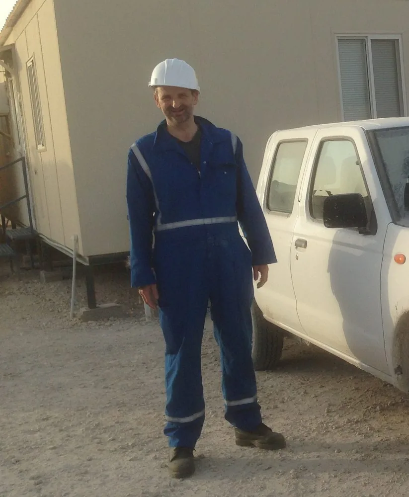
"With the know-how of A. Seitz Ingenieur GmbH, we were able to switch from a discontinued CAD tool to a modern one for plant engineering within a short time."
Engineering firm, plant engineering
General planning
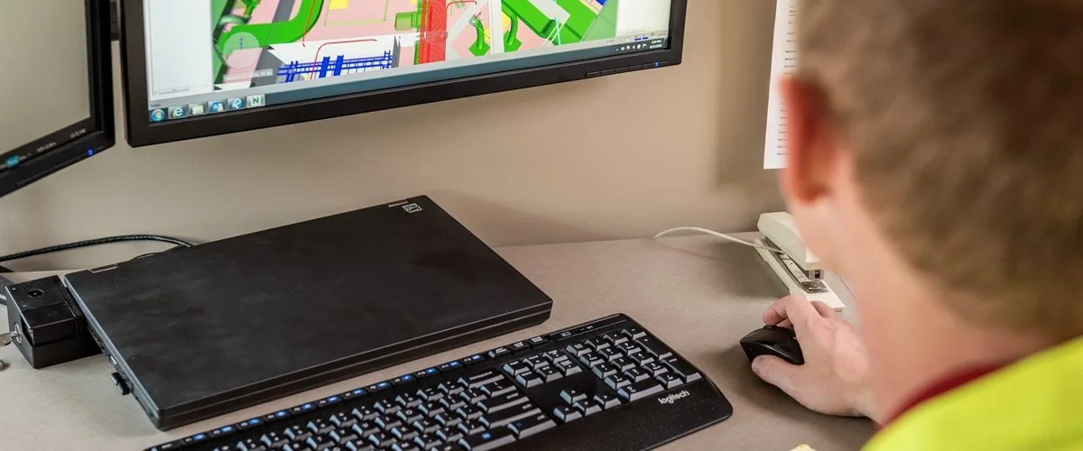
"Fast 3D support in general planning projects without extensive customizing – even in early phases."
Engineering and general planning
How it works
- Enquirytask, scope, date
- Alignmentstandards, data, access
- Executionremote or on site
- Handoverdata & documentation to you
From practice
Two projects – anonymous, with the quantities and hours from our project records, as of 08.10.2026.
Introducing Plant 3D at a chemical company
Scope: 5 projects, about 153 h in total; one project with 23 P&ID drawings.
Result: Deliveries with 42 and 60 PDFs.
From scan to Plant 3D model with isometrics
Scope: 24 scans, 55 detected lines, 71 isometrics, 14 orthos, 39 model drawings, about 65 h.
Result: 104 PDFs in the delivery.
Contact us directly
Write to us or give us a call – we'll get back to you within one business day.
Before you go …
Don't miss any training dates, C³ invitations and news on AutoCAD Plant 3D and P&ID.
Our newsletter only arrives when there's something important – concise and with tips from practice.
Standards status for this page 2 standards · researched October 2026
| Standard | Contents | Current edition | Replaced / successor |
|---|---|---|---|
| DIN EN IEC 81346-1DIN EN IEC 81346 – Industrial systems – Structuring principles and reference designations The cross-industry basis of plant designation: each object under three aspects – function (=), product (-) and location (+). Part 2 contains the code letters, ISO/TS 81346-10 the version for power plants (RDS-PP). Background and sources › | Structuring principles and reference designations – Part 1: Basic rules | DIN EN IEC 81346-1:2024-07 | replaces DIN EN 81346-1:2010-05 |
| DIN EN IEC 81346-2 | Structuring principles and reference designation – Part 2: Classification of objects and codes for classes | DIN EN IEC 81346-2:2020-10 | replaces DIN EN 81346-2:2010-05 |
Researched at DIN Media, ISOISO – International Organization for Standardization International Organization for Standardization in Geneva: it develops standards that apply worldwide (ISO standards). Background and sources ›, IECIEC – International Electrotechnical Commission International Electrotechnical Commission in Geneva: worldwide standards for electrical engineering and for instrumentation and control. Background and sources › and ASMEASME – American Society of Mechanical Engineers US engineering society. Its codes for piping, flanges and pipe dimensions apply in many plants worldwide. Background and sources ›, as of October 2026. Before binding use, please check the current edition with the standards publisher. Overview of all standards: Plant Engineering Infobase · Standards status.
Terms, background and sources 6 terms on this page
Brief explanations for reference. They do not replace the standard or code itself.
- R&I – Piping and instrumentation diagram
Flow diagram showing all pipes, valves, equipment and instrumentation of a plant (P&ID, Piping and Instrumentation Diagram).
Symbols and drawing rules: DIN EN ISO 10628-1 and -2. Identification letters for instrumentation: DIN EN 62424 or ISA-5.1.
- CAD – Computer-Aided Design
Computer-aided design and drafting.
- DIN EN IEC 81346 – Industrial systems – Structuring principles and reference designations
The cross-industry basis of plant designation: each object under three aspects – function (=), product (-) and location (+). Part 2 contains the code letters, ISO/TS 81346-10 the version for power plants (RDS-PP).
- ISO – International Organization for Standardization
International Organization for Standardization in Geneva: it develops standards that apply worldwide (ISO standards).
ISO was founded in 1947. Its members are the national standards bodies; for Germany, this is DIN.
- IEC – International Electrotechnical Commission
International Electrotechnical Commission in Geneva: worldwide standards for electrical engineering and for instrumentation and control.
IEC was founded in 1906. IEC standards adopted in Europe are called “EN IEC …” or “EN 6xxxx”.
- ASME – American Society of Mechanical Engineers
US engineering society. Its codes for piping, flanges and pipe dimensions apply in many plants worldwide.
ASME was founded in 1880. Well-known codes: B31.3 (process piping), B16.5 (flanges), B36.10M and B36.19M (pipe dimensions).
Sources and origins
- ISO – International Organization for Standardization (for R&I, ISO)
- IEC – International Electrotechnical Commission (for R&I, IEC)
- Wikipedia – Computer-aided design (for CAD)
- DIN Media: DIN EN IEC 81346-1:2024-07 (for DIN EN IEC 81346)
- ASME – American Society of Mechanical Engineers (for ASME)