Plant Engineering Infobase · Chapter 13 of 14
As-built capture with laser scanning
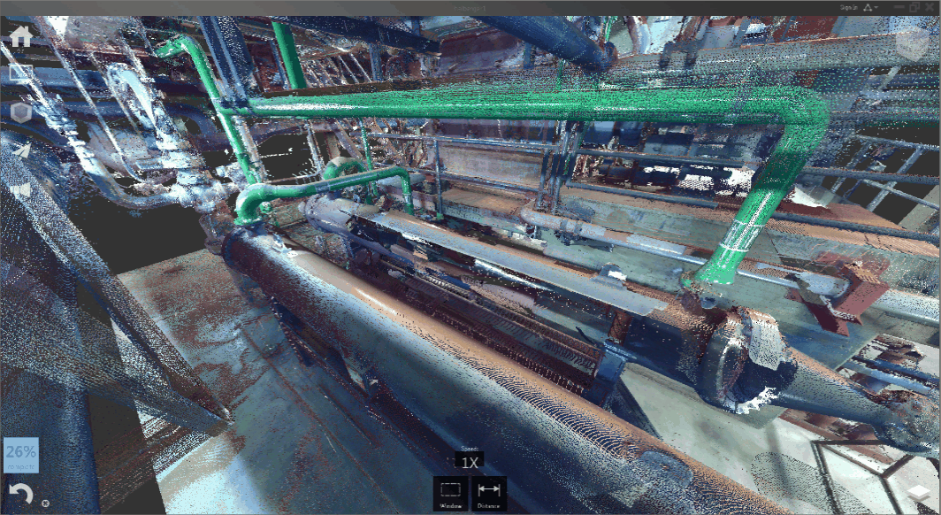
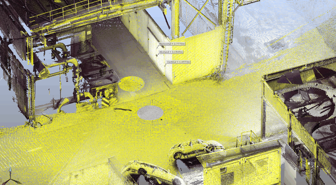
Modifications and extensions of existing plants are best planned on the basis of an up-to-date survey. A 3D laser scanner captures millions of points with coordinates in just a few minutes. Many stations produce a point cloud that serves in CAD as a design basis, for clash detection and for modeling. The key is to plan the scan project with the downstream CAD processing in mind from the start.
Overview
Workflow
| Step | Contents | Tool |
|---|---|---|
| 1 Scan | Choose scanner stations so that the captured areas overlap by around 40%; place reference targets. | e.g., FARO Focus |
| 2 Register | Import scans, remove faulty scans, register automatically, manually link gaps via reference points in adjacent views. | Autodesk ReCap |
| 3 Align | Take the plant origin and drawing orientation (X-axis) from the site or layout plan. | ReCap |
| 4 Structure | Name and assign regions: bounding boxes for machines, planes for walls, piping, equipment. Export regions individually. | ReCap |
| 5 Detect | Convert the point cloud into objects: pipes, steel beams, ventilation ducts, cable trays, walls. | AutoCAD / Plant 3D, EdgeWise |
| 6 Integrate | Combine the point cloud or mesh with the design model, check for clashes, derive isometrics and drawings. | Plant 3D, Navisworks |
Processes and equipment
Existing conditions can be captured in different ways: terrestrial laser scanning from fixed stations, mobile capture from a moving vehicle, drone flights and photogrammetry. In plant and piping engineering, terrestrial laser scanning is the standard because of its accuracy and density.
A scanner such as the FARO Focus weighs around 5 kg and comes with a multi-sensor package: dual-axis compensator (levels each scan, accuracy 0.015°, range ±5°), height sensor (barometer), compass, GPS and Wi-Fi for remote control. With camera, SD card and battery, it works independently of the power grid. EdgeWise and ReCap process scans from all common manufacturers (FARO, Leica, Z+F, Trimble, Topcon); the exchange format is E57.
Planning a scan project
The effort is usually underestimated when based on as-built drawings. A site visit before the quote pays off:
| Design status | Scans |
|---|---|
| Rough estimate based on as-built drawings | approx. 160 |
| Planning after a site visit | approx. 330 |
| Actually performed | 386 |
Example from a project by A. Seitz Ingenieur GmbH.
Resolution, scan duration and point spacing (FARO Focus X series)
The resolution depends on the distance to objects and reference targets. Point spacing increases linearly with distance.
| Profile | Resolution | Credits | Quality | Duration | Point spacing at 10 m | at 20 m | at 50 m |
|---|---|---|---|---|---|---|---|
| Indoor up to 10 m | 1/8 | 10.9 million | 3x | 5 min | 12.3 mm | 24.5 mm | 61.4 mm |
| Indoor from 10 m / outdoor up to 20 m | 1/5 | 28 million | 4x | 8:40 min | 7.7 mm | 15.3 mm | 38.4 mm |
| Outdoor from 20 m, long distances | 1/4 | 43.7 million | 4x | 11:15 min | 6.1 mm | 12.3 mm | 30.7 mm |
| Object HD | 1/2 | 174.8 million | 6x | 1:58 h | 3.1 mm | 6.1 mm | 15.3 mm |
Rules for scanning
Stations
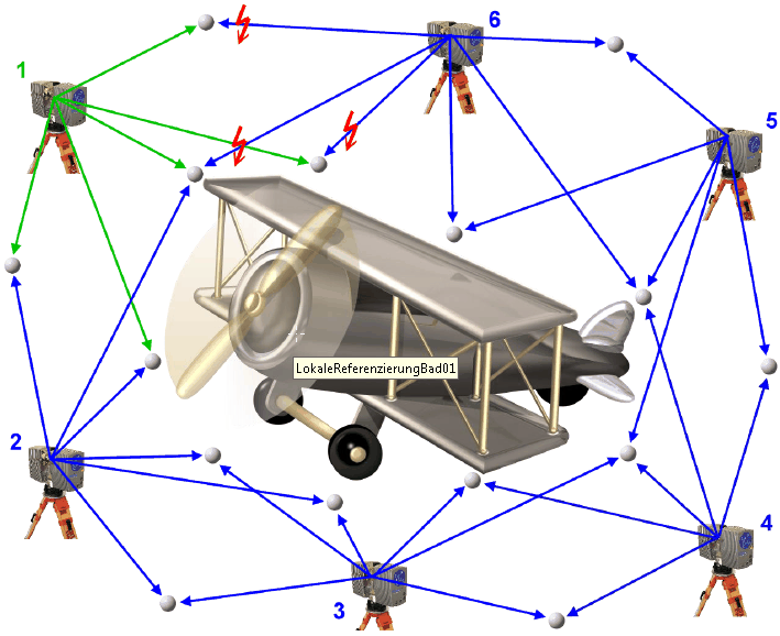
- Captured areas overlap by around 40%
- Place reference targets at different heights and distances
- From every station, 3 old and 3 new targets visible (surfaces can be used too)
- Avoid scan shadows: capture objects from more than 2 stations
- Across floors: several scans in the stairwell
For CAD use
- Always capture a room completely – no "we don't need this area"
- Scan objects from all sides
- Doors and gates with 3 stations: inside, threshold, outside – this lets you check wall thicknesses
- Plan reference scans: stairwells, outside from door to door, walk-through rooms
- Name scans by area already during capture
Environment
- Scanner operating temperature 5–50 °C; wind adds extra cooling – outdoor scans are not practical in every season
- Magnetic drives and high-voltage current can interfere with the scan (compass, sensors)
- Moving objects and people create noise points that have to be cleaned up later
Registration, origin and structure
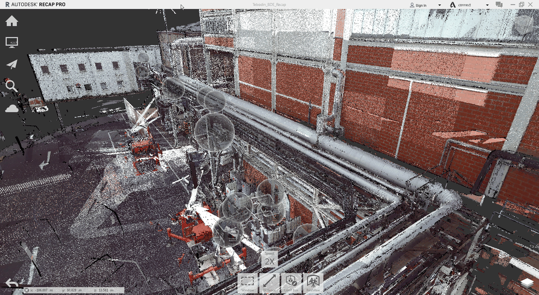
In Autodesk ReCap, a project is created and the scans are imported and checked. Faulty scans are removed, after which ReCap registers automatically; where that fails, scans are linked manually via common reference points in adjacent views.
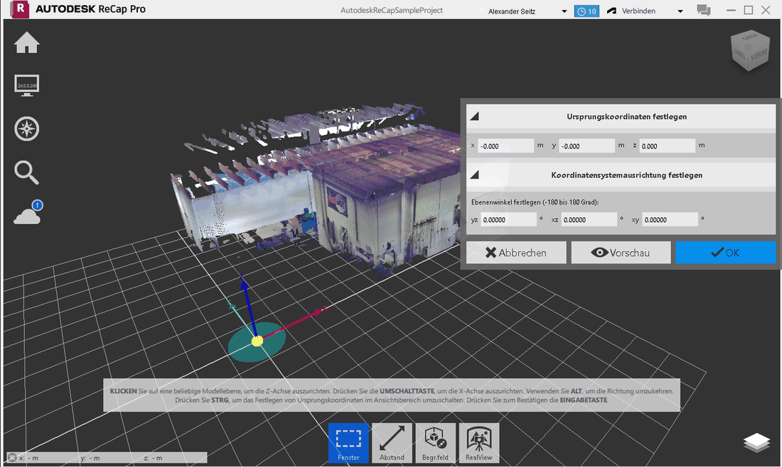
- Align the plant origin and X-axis with the existing site or layout plan. For large plants, a sub-plant origin can be useful.
- Reflect the structure in the scan names in ReCap and assign regions (walls, piping, equipment).
- Export areas: provide individual areas as separate point clouds – smaller data volumes that can also be used on less powerful computers.
- Mesh: current ReCap versions generate a mesh from the scan locally, which is cleaned up and classified in the mesh editor and exported, e.g., to Navisworks.
From point cloud to CAD model
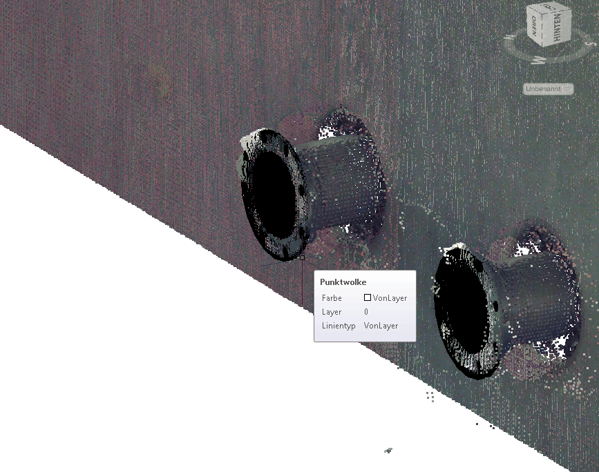
The point cloud is attached in the AutoCAD Point Cloud Manager; AutoCAD and Plant 3D include detection tools for pipes, steel beams, ventilation ducts, cable trays and walls. Often not everything has to be modeled: connections can be placed as connection points directly on the point cloud, and new lines can be connected to them.
Automatic detection with EdgeWise
ClearEdge3D EdgeWise creates objects from registered scans largely automatically. According to the manufacturer, up to 85% of pipes and vessels are detected automatically and the modeling effort is reduced by 50–75%. Components such as valves, flanges, reducers, elbows and tees are placed spec-driven in the correct size, and gaps in pipe runs are closed automatically. EdgeWise also detects steel structures, ducts and walls; export goes directly to Plant 3D, AutoCAD, Revit, CADWorx, MicroStation and PDMS.
Practical values from a project with insulated lines:
| Work step | Note | Duration |
|---|---|---|
| Load scans into ReCap, export as E57 | – | – |
| Process Scans: convert the point cloud into a database | Reduce the point spacing setting | approx. 45 min |
| Pipe detection | Increase the tolerance – the insulation is not exactly round | approx. 15 min |
| Automatic pipe connection (Easy Connect) | closes gaps between detected pipes | – |
| Post-processing | Extract, Edit, Connect straight/tee, Append elbow/pipe, Rotate, SmartSheet | approx. 10 h |
| Export per line | STEP, imported into Plant 3D as Plant 3D objects | approx. 5 min |
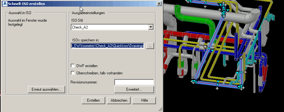
| Isometric | Quick Iso per pipeline | approx. 2 min |
Project examples
| Task | Survey and processing | Handover |
|---|---|---|
| Compare the design status with reality | Building documentation across 4 floors, as-built model from MicroStation combined with the point cloud | Point cloud (ReCap), Navisworks model |
| Renewing plant documentation | Documentation of a modification, modeling in Plant 3D with custom piping specs | Plant 3D piping specs, model, isometrics |
| 2D plant documentation | 3D model with derived views and sections | Plant 3D model, Navisworks model, drawings as PDF |
| Capturing a pipe rack | Detecting the lines with EdgeWise | Plant 3D model |
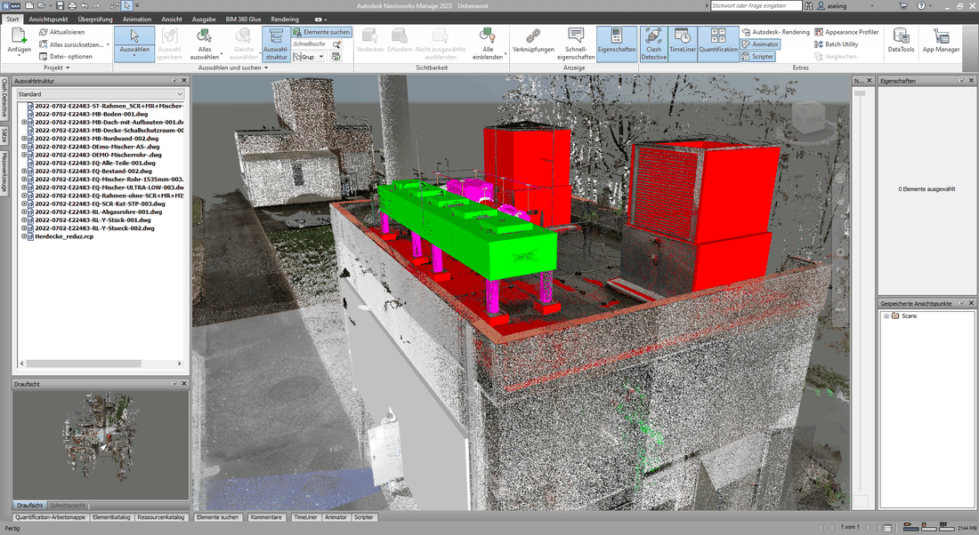
| Catalyst replacement | Survey, design in Plant 3D, engineering review in Navisworks against the point cloud | Design, clash detection |
Related offering
3D laser scanning by ASEING
We plan the scan project with your CAD in mind, scan on site, register and structure the point cloud and, on request, deliver the model in Plant 3D with piping specs, isometrics and a Navisworks model. Training on as-built design, ReCap and EdgeWise on request.
Based on: presentations and project documents by A. Seitz Ingenieur GmbH (planning as-built capture, ReCap, EdgeWise, project examples). EdgeWise manufacturer information: ClearEdge3D.
Overall concept · As-built & laser scan
Software and training for this discipline
Which Autodesk software fits – and where you can learn it. Overview of all disciplines in the overall concept, all dates in the training calendar.
Software
Training dates
Before you go …
Don't miss any training dates, C³ invitations and news on AutoCAD Plant 3D and P&ID.
Our newsletter only arrives when there's something important – concise and with tips from practice.