
Plant Engineering Infobase · Chapter 02 of 14
Flow diagrams
Flow diagrams represent a process schematically. Three types are distinguished by level of abstraction. The governing standards are DIN EN ISO 10628-1:2015 (types, content, presentation rules) and DIN EN ISO 10628-2:2013 (graphical symbols).
Overview
| Type | Purpose and content | Representation |
|---|---|---|
| Block flow diagram BFD | Overview of process stages or plant sections, input and output materials. Optional: material flows, energy carriers, typical operating conditions. | Rectangles connected by flow lines |
| Process flow diagram PFD | Equipment and machines with letter codes, main flow paths, material and energy flows, operating data. The most important document for coordination between the engineering disciplines. | Graphical symbols and flow lines |
| P&ID Piping and Instrumentation Diagram | All pipes with designation (nominal size, fluid, piping spec, insulation), valves, inline components, connection types, slope information and all process control loops with signal lines. Basic document for piping and I&C design. Process parameters are usually omitted. | Symbols according to DIN EN ISO 10628-2 and DIN 28000-4, process control according to DIN EN 62424 |
The P&ID should reproduce the geometric routing of the lines in principle and show the relative heights and sizes of the equipment. Transitions to other sheets are marked with labeled off-page connectors.
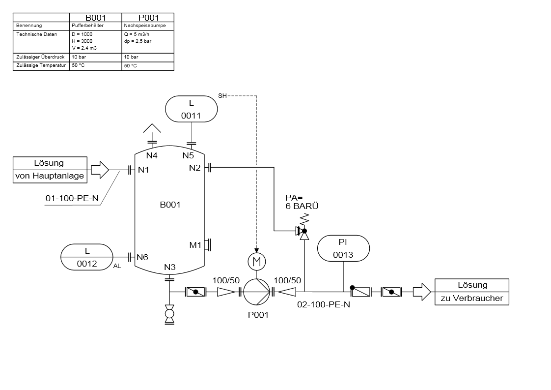
Symbol systems compared
In Germany, P&IDs are drawn according to DIN EN ISO 10628; additional piping symbols are contained in DIN 28000-4 (successor to the withdrawn DIN 2429). In the US, ISA-5.1 applies to instrumentation and PIP symbols (Process Industry Practices) are often used for equipment. JIS symbols are found in Japanese projects.
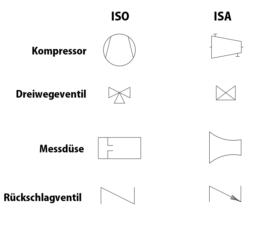
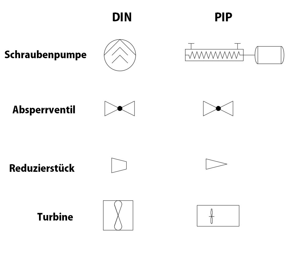
Differences in the American standard
- Data in the US customary system (NPS, inches, psi).
- Equipment symbols represent the external appearance rather than the function; a centrifugal pump and a radial fan therefore look very similar.
- Angle and multi-port valves are distinguished in less detail than under ISO.
- Instrumentation: According to DIN EN 62424, a process control loop with all its functions is handled as one identifier (e.g.
FIRC 101). According to ISA-5.1, devices with their own hardware receive their own symbols, such as transmitterFT 101and controller with indication and recordingFRC 101.
International projects often involve mixed designations. The system used therefore belongs on a legend sheet.
Related offering
ASEING templates – symbols fully configured
The ASEING PlantConfig Pro project templates contain ready-made symbol palettes for AutoCAD P&ID: equipment, packages, I&C, inline assets, valve bodies, lines by fluid and fail position – with a consistent tag structure and mapping between P&ID and Plant 3D.
Company license from €2,490 net plus VAT (tiered by number of Plant 3D users) · 15% less in a package with PlantPlus · individual templates on request
Summary based on Wikipedia: Flow diagram and Wikipedia: P&ID
Overall concept · Process engineering & flow diagrams
Software and training for this discipline
Which Autodesk software fits – and where you can learn it. Overview of all disciplines in the overall concept, all dates in the training calendar.
Software
Training dates

Before you go …
Don't miss any training dates, C³ invitations and news on AutoCAD Plant 3D and P&ID.
Our newsletter only arrives when there's something important – concise and with tips from practice.
Standards status for this page 6 standards · researched September 2026
| Standard | Contents | Current edition | Replaced / successor |
|---|---|---|---|
| DIN EN ISO 10628-1 | Diagrams for the chemical and petrochemical industry – Part 1: Specification of diagrams | DIN EN ISO 10628-1:2015-04 | replaces DIN EN ISO 10628:2001-03 |
| DIN EN ISO 10628-2 | Diagrams for the chemical and petrochemical industry – Part 2: Graphical symbols | DIN EN ISO 10628-2:2013-04 | replaces DIN EN ISO 10628:2001-03 |
| DIN 28000-4 | Chemical process equipment – Documentation in the life cycle of process plants – Part 4: Graphical symbols for valves, pipes and actuators | DIN 28000-4:2014-07 | replaces DIN 19227-1:1993-10; DIN 2429-1:1988-01; DIN 2429-2:1988-01 |
| DIN EN 62424 (VDE 0810-24) | Representation of process control engineering requests in P&I diagrams and data exchange between P&ID tools | DIN EN 62424 (VDE 0810-24):2017-12 | replaces DIN EN 62424 (VDE 0810-24):2010-01 |
| DIN 2429-1 | Graphical symbols for technical drawings; pipelines; general | withdrawn | now: DIN 28000-4:2014-07 |
| ANSI/ISA-5.1 | Instrumentation and Control – Symbols and Identification | ANSI/ISA-5.1-2024 | replaces ANSI/ISA-5.1-2022 |
Researched at DIN Media, ISO, IEC and ASME, as of September 2026. Before binding use, please check the current edition with the standards publisher. Overview of all standards: Plant Engineering Infobase · Standards status.