
Plant Engineering Infobase · Chapter 12 of 14
Project Setup in AutoCAD Plant 3D
The goal is a template project with usable layouts, a plant identification system (here KKS) in the tag assignment, automatic annotation and symbols according to DIN and ISO. First collect all requirements, then work through them according to the schedule.
Overview
The most important point is consistent tag assignment in P&ID and Plant 3D: every piping spec assigned in the P&ID must exist in Plant 3D, and every P&ID symbol needs a matching component in the piping spec. Check views must be in place.
Related offering
Abbreviation
ASEING PlantConfig Pro delivers the setup described here – with KKS, AKS, RDS-PP or DIN EN ISO 10628, title block, annotation and check views – fully configured: as a company license from €2,490 net (tiered by number of Plant 3D users), individual templates on request.
Project data
| Project name | Client_ProjectName_ProjectNumber |
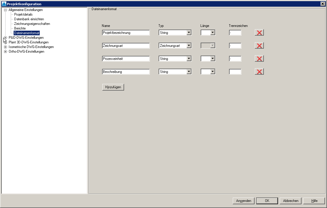
| Drawing name | ProjectNumber_DrawingType_Number_ShortName |
| Project participants | Addresses and contacts for client, designer, architect, inspector, structural engineering |
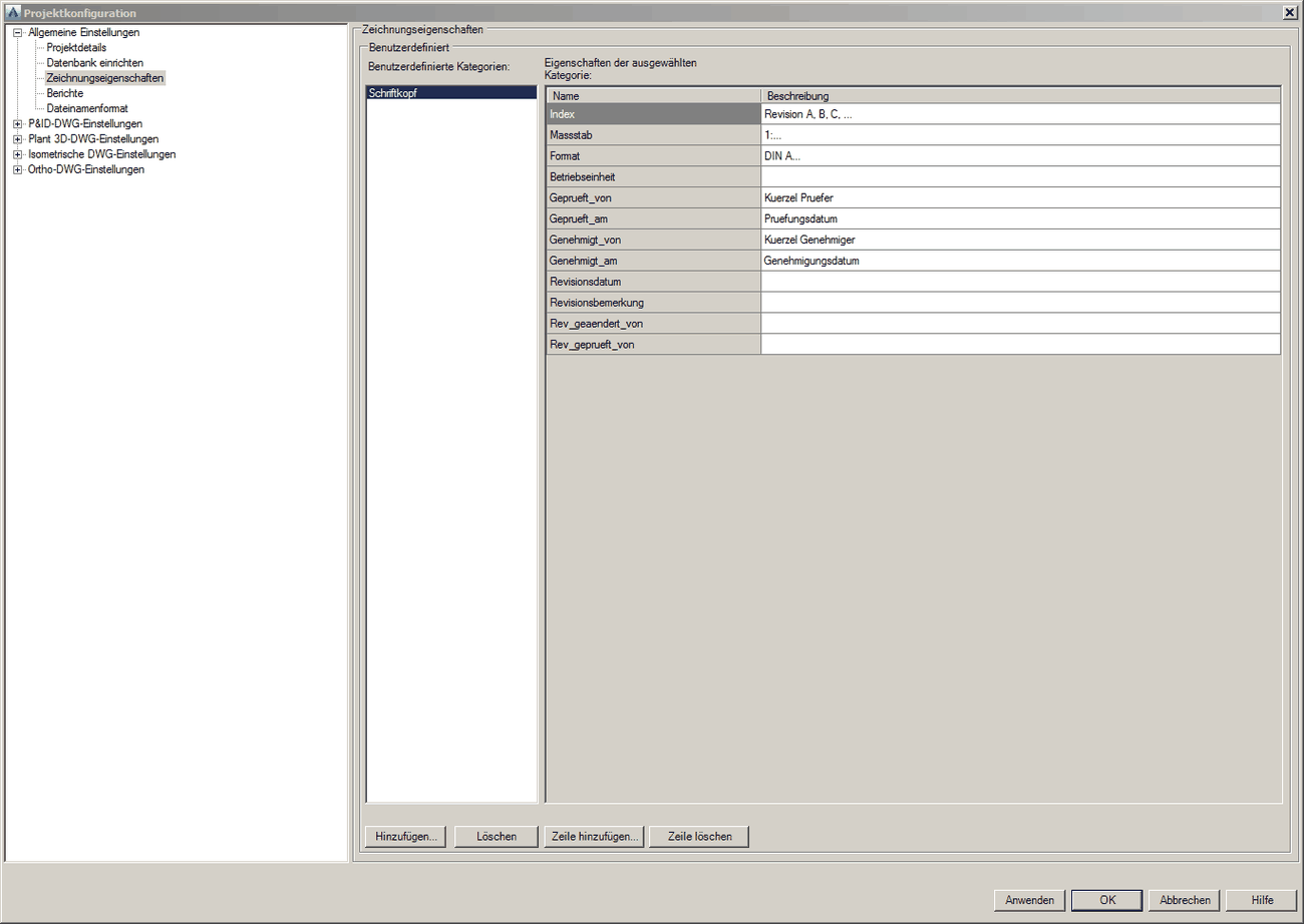
| Title block | Always fill in quality information: created by, checked by, approved by |
Fields, tags and annotation
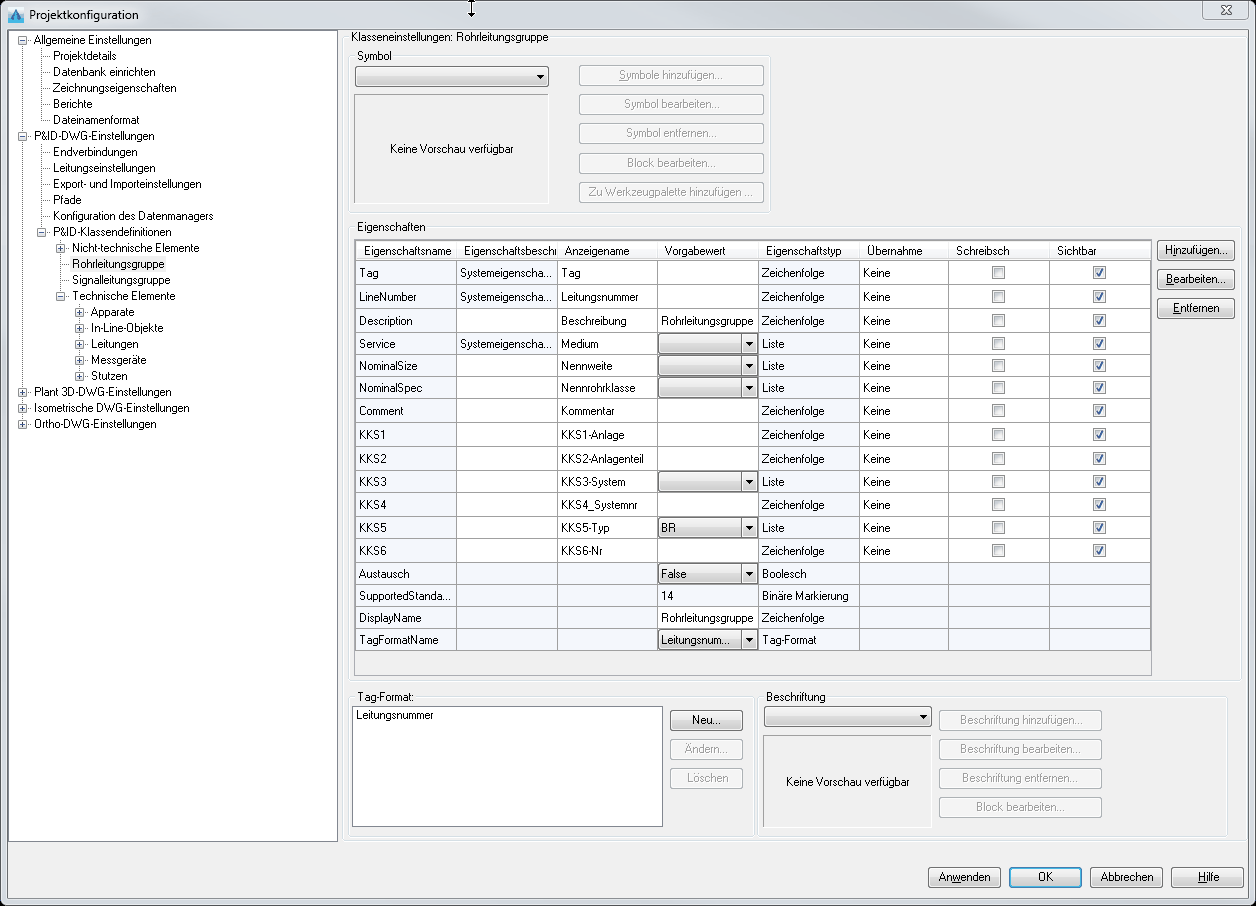
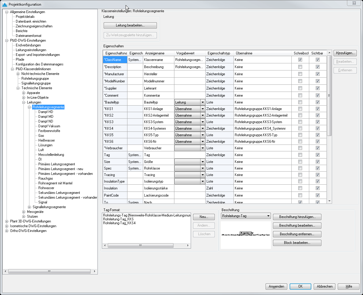
Field definitions and selection lists are the basis for tags, annotation and material takeoff. Standardize tag definitions across all classes and generate annotations exclusively from properties.

Comparing P&ID and Plant 3D
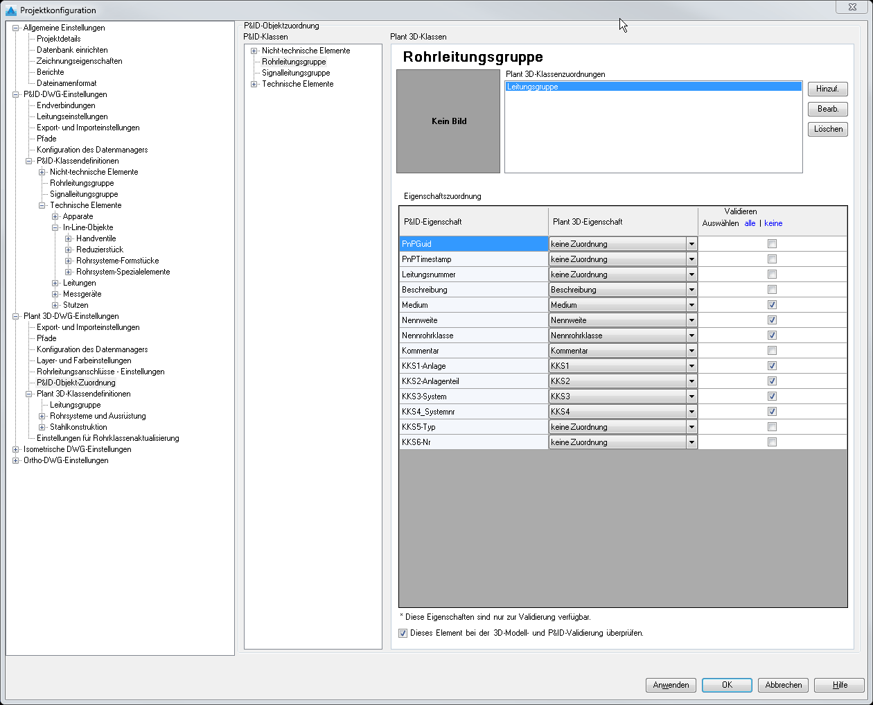
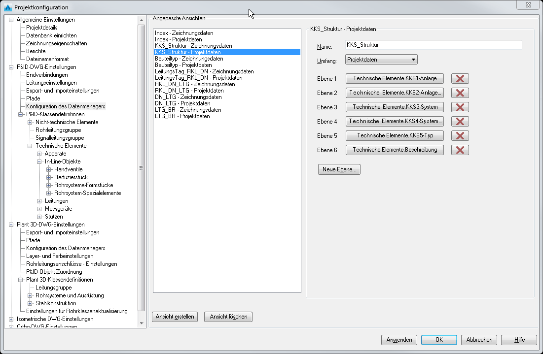
Tags and fields must have the same names in both environments and be linked via property mapping. Maintain the mapping list of P&ID objects to 3D objects. Create check views for tags and annotation in the Data Manager; reports show at a glance which symbols have already been placed in the 3D model.
Lines, symbols, catalogs
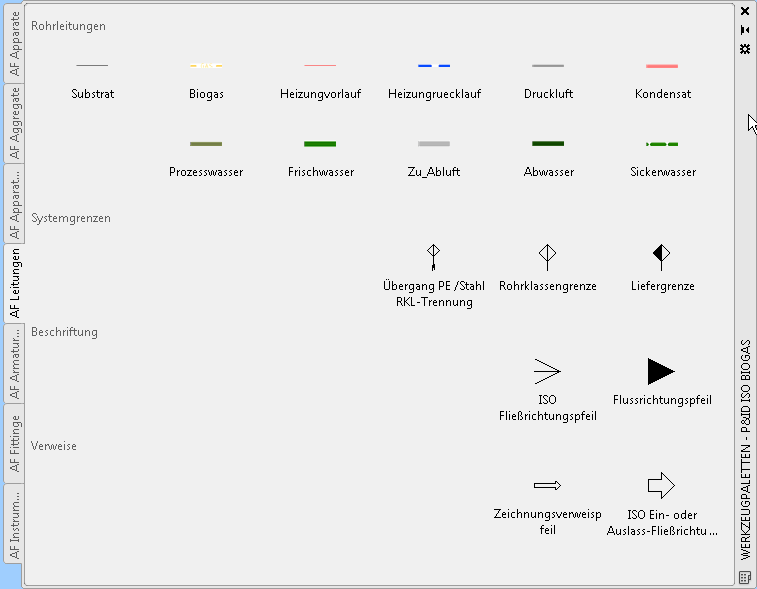
- Line definitions: distinguish lines by fluid using linetype and color. The scheme is a project standard; DIN 2403 applies to color coding on the built plant.
- Symbol library: configure symbols so they can be linked to 3D objects; organize tool palettes logically (equipment, valves, lines, instruments).
- Material catalogs and piping specs: duplicate existing, working components instead of creating new ones. Catalogs can also be assembled via the clipboard.
- Bills of materials: align the content with the intended use (purchasing, fabrication, installation).
Related offering
Ready-made symbol library
The ASEING templates (PlantConfig Pro) provide organized tool palettes (equipment, valves, I&C, lines) with P&ID-to-3D mapping – as a company license from €2,490 net (tiered by number of Plant 3D users), individual templates on request.
Documenting the configuration
Record every deviating configuration in the project configuration template. This includes:
- Installation notes: administrator rights, paths, virus scanner; connection to company-specific standards, central DWT templates and central piping specs.
- Project setup guide: create the project, adjust paths, check or import tool palettes, update project-specific fields immediately.
- Work instructions for users: valid symbols, annotations to use, mandatory information, checks before submission, data exchange.
Related offering
Learn to set it up yourself
Level 2 "Administrator" of our training program covers the project, symbol library, data and annotation in Plant 3D. Or get it ready-made: ASEING PlantConfig Pro and the ASEING PlantPlus functional extension.
Overall concept · Process engineering & flow diagrams, piping construction
Software and training for these trades
Which Autodesk software fits – and where you can learn it. Overview of all disciplines in the overall concept, all dates in the training calendar.
| Discipline | Software | Training dates |
|---|---|---|
| Process engineering & flow diagrams | AutoCAD Plant 3D & P&ID AutoCAD (incl. toolsets) | AutoCAD P&ID Fundamentals AutoCAD P&ID Setup |
| Piping construction | AutoCAD Plant 3D & P&ID Navisworks Inventor | AutoCAD Plant 3D Fundamentals Plant 3D Piping Spec Workshop Plant 3D Configuration & Data Management Inventor Compact: Tube and Pipe |

Before you go …
Don't miss any training dates, C³ invitations and news on AutoCAD Plant 3D and P&ID.
Our newsletter only arrives when there's something important – concise and with tips from practice.
Standards status for this page 3 standards · researched September 2026
| Standard | Contents | Current edition | Replaced / successor |
|---|---|---|---|
| DIN EN ISO 10628-1 | Diagrams for the chemical and petrochemical industry – Part 1: Specification of diagrams | DIN EN ISO 10628-1:2015-04 | replaces DIN EN ISO 10628:2001-03 |
| DIN EN ISO 10628-2 | Diagrams for the chemical and petrochemical industry – Part 2: Graphical symbols | DIN EN ISO 10628-2:2013-04 | replaces DIN EN ISO 10628:2001-03 |
| DIN 2403 | Identification of pipelines according to fluid conveyed | DIN 2403:2025-12 | replaces DIN 2403:2018-10 |
Researched at DIN Media, ISO, IEC and ASME, as of September 2026. Before binding use, please check the current edition with the standards publisher. Overview of all standards: Plant Engineering Infobase · Standards status.